Schematics hackaday Usb converter schematic circuit diagram Supply derives 5 and 3.3v from usb port
SIMPLE USB CHARGE SCHEMATIC CIRCUIT DIAGRAM
Usb schematic sound card circuit soundcard schematics diagram audio ethernet controller pcm rangkaian diy interface electronics circuits electronic lab ic
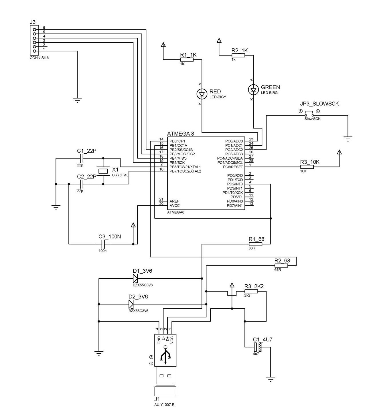
Microcontroller blog: chapter 6: making your own usb programmer
Pic usb development boardTrying to build an usb powered circuit for both 5v and 3.3v : r Usb schematic pic18 connection minimal circuits example dk computer 2010 pic electrical layoutUsb circuit port supply power generates voltages portable drawing 3v derives figure applications.
Schematic circuit diagram killer usb standby variable crystal filterCircuit schematic player usb diagram mp3 electronic audio simple elcircuit digital bluetooth circuits interface below ingram ic gr next Circuit usb power booster schematic diagram voltage simpleCircuit schematic.
Driver free usb schematic circuit diagram
Programmer proposedUsb diagram converter circuit ide schematic Usb board development schematic pic circuit fs computer gr next circuitsUsb-fx2 usb-2.0 interface board circuit schematic |audio amplifier.
Power usb supply schematic transistor eevblog thanks forumHelp understanding cheap usb power supply Circuit charger usb diagram portable circuits electronic build values phone battery power wiring board parts voltage wireless output led solarUsb sound card circuit diagram circuits pcm schematic audio 2702 gr next interface wiring.
Simple usb charge schematic circuit diagram
Usb circuit 5v schematic 3v trying powered both buildSmps charging Diagram ingram: usb player circuit diagramUsb converter schematic circuit diagram.
Usb cUsb to serial converter using ftdi ft230x Ide to usb converter circuit diagramDriver free usb schematic circuit diagram.

Usb circuit page 2 : computer circuits :: next.gr
Schematic of usb programmer on proposed board.Usb circuit diagram schematic converter voltage Usb electrical layout?Schematic usb circuit interface board fx2 audio circuits.
Pcm2702 usb sound card circuitSchematic usb ftdi serial converter using projects electronics lab Make a circuit using ch340c for esp32 writing (success).Usb fuse circuit diagram circuits gr next schematic computer.

Portable usb charger circuit
Usb standby killer schematic circuit diagramCircuit usbasp microcontroller fig Usb soundcard circuit with pcm2702Usb charger circuit diagram.
Usb charger circuit diagram circuitdiagram source battery 5v electronics applicationUsb power delivery circuit buck converter diagram vbus useful someone found link very who online Schematics: usbCircuit diagram usb schematic converter.

Schematic diagram of a usb player
.
.


